
Sponsored by Pickering Interfaces.
Herein, we discuss the goals of BMS verification and explain how simulation with hardware-in-the-loop provides a wealth of data, saves time and is safer than working with actual live cells. We also explain how a BMS HIL test system can be created using PXI simulation modules from Pickering Interfaces.
Battery Management Systems (BMS)
Electric vehicle (EV) battery packs – which can contain from a few dozen to more than 1,000 cells – must be controlled for optimum performance in terms of releasing and accepting power. The packs must also be monitored to report SoC and SoH (state-of-charge and -health, respectively) to the systems employing them. Also, safety measures/features must be present to isolate the packs (or modules/banks of cells) in case of a fault. These roles are all performed by the BMS.
Safety
Safety is a vital consideration wherever battery packs are used. In automotive applications, the packs and all vehicle/platform components that electrically connect to them (including the BMS) are considered hazardous items and must comply with ISO 26262.
BMS Design & Verification
Most companies adopt a TDD (test-driven development) strategy when designing a BMS. This enables them to not only optimize the battery pack’s size (both physical and energy capacity), but also verify the functionality of the BMS throughout the product development lifecycle.
Typical top-level functional requirements for a BMS include:
- Voltages must be monitored at the battery pack’s inputs and outputs, and at the individual cell level.
- Current flow into and from the pack must be monitored.
- SoC and SoH should be monitored and made available to systems that draw power from the pack and which charge it.
- Thermal management – for example, lithium-ion cells perform best between 10 and 45oC, so the BMS must control the heating or cooling of the pack accordingly.
- The BMS must protect against in-use conditions, such as over-charging and fault conditions (like an individual cell failing or wires breaking). It must also protect against human errors, such as getting the polarity wrong during a maintenance or repair task.
Verifying through test that the above requirements and others have been met is more than just a development task, however. Every production unit must be functionally verified as part of its quality assurance.
Simulation with Hardware-in-the-Loop
BMS development with HIL (hardware-in-the-loop) is essential. However, the use of an actual battery pack presents challenges, including:
- Performing over-voltage checks is dangerous – with the risk of fire or explosion.
- It’s not easy to change the voltages of individual cells, meaning it’s difficult to verify that the BMS’s cell balancing function works.
- Where the monitoring of individual cell voltages is concerned, it’s only possible to check what the BMS thinks it is seeing. But what are the real cell voltages?
- How can the BMS’s temperature monitoring function be checked without subjecting the pack to dangerous temperature extremes?
There is also the issue of test repeatability and documenting test conditions and results. Test set-up and the reporting of results are both open to human error. This means the accuracy (and by extension, validity) of the BMS verification data could be called into question.
The solution to these issues is simulation. It removes the need to work with live cells, making it safer. The voltages supplied to the BMS in lieu of individual cells can be monitored, so there are values against which the BMS’s observations can be compared.
Simulation is also highly repeatable, as fault conditions, such as broken wires and overheating cells, are far easier to simulate than they are to replicate with live cells. The recording of test conditions (stimuli applied) and results are straightforward.
High Voltage Switching
Pickering Interfaces’ PXI high voltage switching modules support hot switching of 0.25A at up to 7.5kV (DC and AC peak) and cold switching up to 9kV (DC and AC peak). Also, 5A can be hot switched at up to 1kV.
Battery Cell Simulation
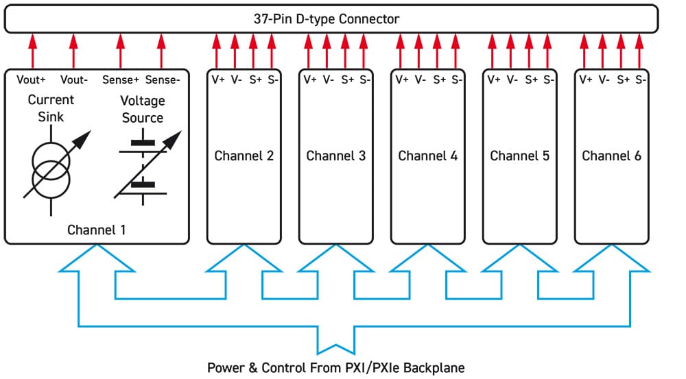
Pickering’s PXI/PXIe multi-channel battery simulator module (Figure 1) was created with BMS design and verification in mind. The module comprises power supply channels (two, four or six per slot) capable of supplying up to 7V and 300mA isolated from one another and from ground. The power supplies on the module can therefore be used to emulate a stack of battery cells which, as mentioned, the BMS must be proven to monitor on an individual cell basis. Also, each channel can sink up to 300mA to emulate a battery under charge. Each channel provides independent power and sense connections, allowing the simulator to sense a remote load and correct for wiring losses.
RTD & Thermocouple Simulation
RTD (resistance temperature detector) simulators can emulate the behavior of positive or negative temperature coefficient thermistors, for example, the PT100 resistance temperature sensor (with a resistance of 100Ω at 0oC), which is commonly employed in battery packs.
Pickering has PXI simulator modules (with 4, 8, 12, 16, 20 and 24 channels) that can simulate the resistance range 40 to 900Ω, which equates to a temperature of -150 to 850oC, to a resolution of less than 10mΩ.
Thermocouples are also employed in battery packs, particularly during product development, because of their high accuracy. These too can be simulated during the development and verification of the BMS ahead of its connection to (or integration within) an actual battery pack.
Pickering has a range of PXI millivolt thermocouple simulator modules that provide 8, 16, 24 or 32 channels of highly accurate low-voltage sources. Each channel can be operated over three voltage ranges to simulate the three most common thermocouple types in use.
Fault Insertion
Pickering’s range of PXI fault insertion units (FIUs) – also known as fault injection switches – is designed specifically for safety-critical applications where the behavior of a control system, such as a BMS, needs to be fully evaluated.
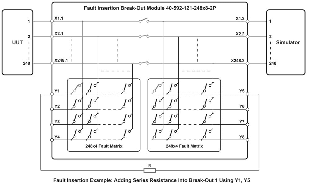
For example, the 40-592 FIBO (fault insertion break-out) is a large-scale, high-density switching matrix. It is one of a range of modules designed for applications requiring the simulation of various faults in complex designs that feature a high number of signals/connections – a battery pack being a prime example. Typical faults that can be simulated are open circuits and short circuits to either another signal/component or to ground (see Figure 2).
BMS HIL Test System
A comprehensive HIL test system for BMS verification can be created using PXI/PXIe-based modules (see Figure 3 and Video):
- Battery Cell Simulator – simulates each cell’s voltage and current output and has individual current sinks to emulate cell charging.
- Fault Insertion Switching – simulates short- and open-circuits on each battery cell output, as well as wiring faults between cells and the BMS. Polarity reversal can also be tested (to verify that the BMS would recognize a manufacturing defect, such as an inverted cell in the pack).
- Charge Emulation – programmable current source.
- COMMS – the ability to send commands to and receive data from the BMS (in automotive applications, typically using CAN bus).
- Load Emulation – programmable resistive load to emulate battery stack loading.
- Temperature Sensor Simulation – provides the BMS with inputs from RTDs or thermocouples.
- Isolation Resistance Simulator – verifies the BMS’s electrical isolation monitoring function.
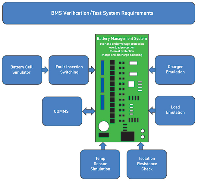
Together, this test system can be used in a variety of permutations to replicate all the standard operating conditions the BMS and battery combination are designed to cope with, and to verify that the BMS performs all its functions, including cell balancing, voltage and current monitoring, cell balancing, temperature monitoring, reporting faults and taking appropriate measures.
Summary
Simulation is the safest way to verify that a BMS’s features perform as intended – because it doesn’t involve creating over-voltage or short-circuit conditions with live cells. It is also easy to replicate open circuits and temperature extremes.
A comprehensive HIL test environment can be created using COTS PXI-based simulators, emulators and fault insertion switches, where the popular and industry-standard PXI platform provides modularity, flexibility, and scalability.
Importantly, for traceability and certification purposes, simulation provides more meaningful data that is easy to capture and record.


